
The Amstrad PC1512 - Britain’s Answer To IBM’s PC
In 1986 Alan Sugar’s Amstrad released the PC1512, their 8MHz 8086-based PC compatible. Sporting 512KB of RAM, a 5.25” floppy drive, MS-DOS 3.2 with the GEM windowing system (this was pre-Windows, remember) and plenty of options including 10MB or even 20MB hard drives, a dot matrix printer, a modem, and more besides, the system was a real low cost contender and was a good seller despite rumoured reliability issues.
The PC1512 also included Amstrad’s own PC-MM (CGA grayscale) or PC-CM (16-colour CGA) monitor. The custom graphics chipset was CGA compatible and actually offered an enhanced CGA mode which allowed all 16 colours to be usable (at the same time!) at CGA’s maximum resolution of 640x200. Whichever monitor the machine was specced with, it connected via a proprietary 8-pin DIN socket to carry the video signals, and a 14-pin DIN connector to carry power to the base unit.
…wait, what?
Yes, that’s right. One of Amstrad’s many notorious cost-cutting measures, the engineers figured that, as the monitor needed to generate 5V and 12V internally anyway, why not just feed that down a cable to the computer itself and save the cost of a whole extra PSU?
And you know what? It worked.

Well, it worked until the monitor died, or if you were one of the many people who bought the grayscale PC-MM to predominantly use the system for word processing, only later wanting to upgrade to a colour monitor for games.
I recently found myself a victim of both of these issues - with a dead PC-MM on my hands, and an unexplainable desire to preserve this weird XT-class machine, I decided to try to rig something up. I’d read on the internet that it was possible, and even seen a few mentions of people doing this back in the 80s… But with nothing concrete available I pretty much had to figure things out for myself.
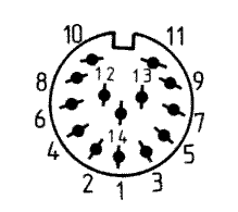
Amstrad PC1512 Power Pinout
Pictured below is the power plug (from monitor) taken from the PC1512 service manual. Note that, as this diagram shows the monitor plug, the socket on the PC will be the mirror image. If in doubt the pins are labeled on the socket itself and on the bottom of the motherboard. The pinout is the same for the PC-CM and PC-MM.
| Pin | Function | Wire Colour * | Pin | Function | Wire Colour * |
|---|---|---|---|---|---|
| 1 | Not Connected | N/A | 8 | GND | Black |
| 2 | GND | Black | 9 | -12VDC | Blue |
| 3 | +5VDC | Red | 10 | GND | Black |
| 4 | GND | Black | 11 | +12VDC | Orange |
| 5 | +5VDC | Red | 12 | GND | Black |
| 6 | Not Connected | N/A | 13 | -5VDC | White |
| 7 | Not Connected | N/A | 14 | Not Connected | N/A |
Anyone familiar with an AT power supply should be familiar with these connections. In fact, that’s exactly what I used to construct my Amstrad PC1512 external power supply - an old AT PSU that had been hacked about over the years.
Note that the 5V connections are doubled up just as per a standard AT or ATX power supply. This is because of limitations on the amount of current per wire, and the 5Vs are tied together at the motherboard end anyway.
* Please confirm with a multimeter, these were the colours of my wires but yours could be different!
Notes on -12VDC and -5VDC
I wasn’t familiar with the concept of negative voltage at the outset of this project, and you might not be either. To be honest, it’s not really important and it’s out of scope to explain it all here. What is important is how the PC1512 uses these negative power rails - which is to say not at all. They are wired directly to pins 5 and 7 on the non-component side of the ISA slots as you might expect, but the PC doesn’t use these voltages anywhere internally. If you’re not planning on using ISA cards, or you know for a fact that the cards you are using don’t use -5VDC or -12VDC, you can safely skip these connections. I decided to wire them up anyway in the name of completeness.
The original AdLib cards use -12VDC for example, as do some network cards. AFAIK nothing uses -5VDC, and it was actually removed fairly early on in the ATX spec for this very reason.
On that note, I have actually seen PSUs added to PC1512s by just plugging a floppy connector directly into CP105, which is a pin header next to the power socket. I don’t recommend this approach however, as it could have unintended consequences (in addition to the potential ISA issues). For example, computers with a lot of periperals could end up drawing a lot of power through these pins, causing damage to the motherboard or even creating a fire hazard.
Update - Notes on Wattage and PSU Suitability
I have been contacted by a gentleman who has been attempting to follow this guide using an Apple II PSU. I think this is a fantastic choice as it is very compact and certainly has the “retro” factor. Sadly, however, the original Apple II was never intended to support an internal mechanical HDD and the PSU therefore can only deliver 63W. His machine (actually a PC1640) was otherwise running fine with the Apple power supply but his hard drive was not spinning up as expected, and we eventually decided that this was due to a lack of wattage.
I do run an XT-IDE with a CompactFlash card in my IBM 5150, another XT machine with a 63W power supply, and it works just fine. But if you are intending on running a mechanical HDD from the same supply I would highly recommend going with either a later hard drive with lower power requirements, or a PSU capable of delivering at least 200W.
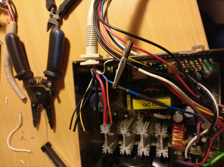
Wiring The PSU
I started by desoldering all unnecessary wires from the PSU, including all of the drive connectors. What we need are the wires connected to the P8 and P9 AT connectors, which are wired up as follows:
| P8 Pin | Function | Wire Colour | P9 Pin | Function | Wire Colour |
|---|---|---|---|---|---|
| 1 | Power Good * (+5VDC) | Orange | 8 | GND | Black |
| 2 | +5VDC | Red | 9 | GND | Black |
| 3 | +12VDC | Yellow | 10 | -5VDC | White |
| 4 | -12VDC | Blue | 11 | +5VDC | Red |
| 5 | GND | Black | 12 | +5VDC | Red |
| 6 | GND | Black | 13 | +5VDC | Red |
As you can see we have some wires to spare here - I just desoldered the extras to keep everything tidy. The other good news (in my case at least) was that the colours all matched up pretty exactly. Now it’s just a case of splicing the wires together (solder - not the ol’ “twist and tape”) and insulating the joint with heat shrink. This makes for a tidy, professional job.
One last step before whipping out the soldering iron is to test the output of every single wire with a multimeter. This is a good time to calibrate your PSU. I found that my 12V was reading at about 10V, but this could be adjusted by turning a potentiometer inside the PSU with a small flat screwdriver. Hopefully I don’t need to tell you to be careful!
* “Power Good” should only output 5V once the power supply has warmed up (a matter of milliseconds), signalling to the computer that the power is clean and it is safe to turn on. After some probing I decided not to connect this to anything as the Amstrad doesn’t seem to use it anyway. Just be sure to use a good quality PSU.
Testing
Before plugging in, it’s a good idea to test every single pin of the connector with your multimeter again. It would be a shame to get this far and blow up a priceless 8086 machine. Then we’re good to go!
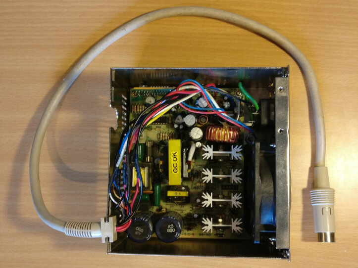
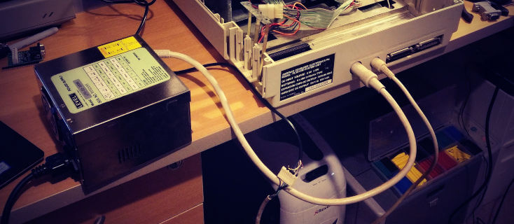
…and here’s the finished article!
Of course we’re not fully liberated from that monitor just yet, but hooking up comfirmed that the system powered on, checked the drives and beeped as expected. I stuck an IBM CGA card into one of the ISA slots and checked the output on an external monitor to confirm that things were working as expected. I could just leave it at that, but I really want to use the onboard graphics - which can’t be disabled to prevent potential conflicts - and also to preserve some semblance of originality. Not to mention the fact that 8-bit ISA graphics cards are getting hard to come by.
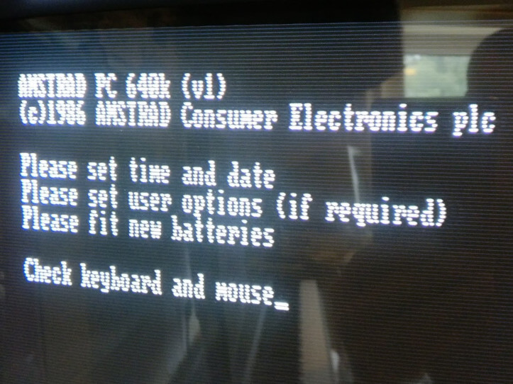
This is also how I discovered that this machine had been upgraded to 640k… And that’s not where the upgrades end. But that’s for another time.
So tune in next time to find out how I eventually manage to hook up the weird graphics output - here’s a hint: It’s TTL RGBI (separate R, G, and B and Intensity) like CGA, but with a composite sync signal, very much unlike CGA…
If you liked this post please consider following me on Instagram or BlueSky!