
The Amstrad PC1512 - Video Nasties
So we went over the general weirdness of the Amstrad PC1512 in my previous post about building a nice external power supply for it. But that’s not a lot of use if we can’t see the video output! So in this post I’m going to cover my progress so far in getting a usable output on a modern monitor.
I’m going to be using a Gonbes GBS-8200 video upscaler, a cheap and cheerful Chinese “CGA to VGA” converter popular with the arcade community. Except of course that in this case, “CGA” doesn’t mean what we think it means, as the GBS 8200 actually accepts an analog 15kHz input with a composite sync.
This is not CGA - however, it is pretty much what we’re already getting out of the Amstrad! Happy days!
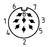
Amstrad PC1512 Video Pinout
Pictured below is the video plug (from monitor) taken from the PC1512 service manual. Note that, as this diagram shows the monitor plug, the socket on the PC will be the mirror image. If in doubt the pins are labeled on the socket itself and on the bottom of the motherboard. The pinout is the same for the PC-CM and PC-MM.
| Pin | Function | Wire Colour * |
|---|---|---|
| 1 | Composite Sync1 | White |
| 2 | Intensity2 | Yellow |
| 3 | GND | Black |
| 4 | Black3 | Grey |
| 5 | Green | Green |
| 6 | Blue | Blue |
| 7 | GND | Black |
| 8 | Red | Red |
1Unlike standard CGA, the Amstrad outputs a composite horizontal and vertical sync signal.
2Much like CGA, the “Intensity” pin signals whether to output a second “intense” version of one of CGA’s 8 colours, meaning that we can address 16 colours in total.
3There is some speculation as to the purpose of the “black” pin, but I haven’t been able to find any definitive answer. It seems it has something to do with Amstrad’s PC-MM grayscale monitor, and appears to be wired into the contrast control, so it probably isn’t of much interest for our purposes.
* Please confirm with a multimeter, these were the colours of my wires but yours could be different!
Hooking Up To The GBS-8200
I connected the R, G, B, and sync signals directly into my GBS-8200 to get a feel for what we’re dealing with here. As you can see, the output is actually weirdly inverted. We need to build an inverter circuit - but first a note on…
Getting Video Out - A DIY CGA-ish Connector For The PC1512
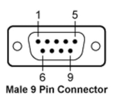
I have the original monitor cable and I could’ve used that to hook up to. I’ll probably build this into an external box once the circuitry is all finalised. But for ease of experimenting I actually bought a cheap VGA breakout adapter from ebay and soldered up some wires to the video connector pins on the bottom of the motherboard. The actual order of the pins doesn’t matter too much as it’ll be going into a homemade adapter, but to make my life easier I wired it up similar to CGA, except with the composite sync on pin 9 and the “black” on pin 8.
If you have a 9-pin CGA video cable you could chop that up instead.
| CGA Pin | CGA Function | Amstrad Pin | Amstrad Function |
|---|---|---|---|
| 1 | GND | 7 | GND |
| 2 | GND | 3 | GND |
| 3 | Red | 8 | Red |
| 4 | Green | 5 | Green |
| 5 | Blue | 6 | Blue |
| 6 | Intensity | 2 | Intensity |
| 7 | Reserved | - | Reserved |
| 8 | Horizontal Sync | 4 | “Black” |
| 9 | Vertical Sync | 1 | Composite Sync |
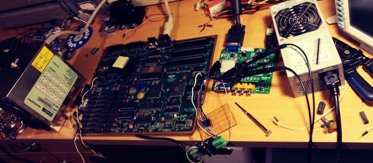
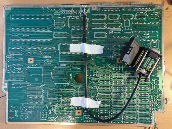
Below you can see the physical manifestation of my efforts. I’m planning on hiding all of the video conversion circuitry under the floppy drives at the front of the PC, so I ran the cable there and secured it to the bottom of the motherboard with tape to stop any tension on the solder joints.
Consulting The Original Schematics For Clues
I had a pretty good discussion over on the Vintage Computer Club group on Facebook and had some great input in particular from Antony T Curtis and Andrew Gostling. It turns out Andrew is quite active in the Spectrum modding scene in particular, but had actually built one of these PC1512 converters in the distant past and since misplaced it. Ultimately it was him who clued me into the need for the inverter in the first place.
After a few days of experimenting with a CD74HCT14E Schmitt inverter and not really getting anywhere, I stumbled across the following schematic on page 43 of the Amstrad PC1512 / PC-MM / PC-CM Service Manual:
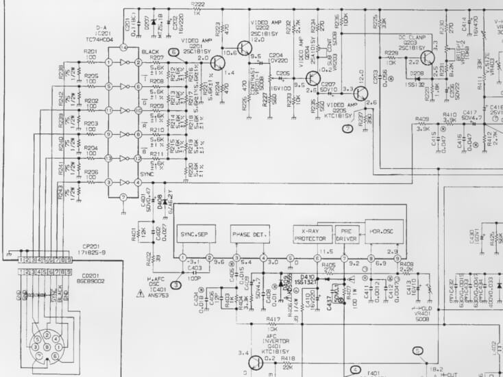
This shows part of the video circuitry for the PC-MM and PC-CM monitors, and anyone who’s looked at a datasheet for an inverter IC (as I had been) will instantly recognise the big rectangular component in the top left! It turns out Amstrad used a Toshiba TC74HC04 hex inverter chip, which is similar enough to my chip and also pin compatible, so not the source of my issues. What they do have are 75Ω pulldowns and 100Ω resistors on the inputs. Bingo!
On the output side, we can basically see the R, G, B, I, and black signals being combined into a composite signal and then passed through an amplifier. This would be useful for anyone wanting to hook one of these up to a composite TV or monitor (although RGB SCART might be a better option).
For our purposes we can just connect the outputs of the inverter directly to the GBS-8200, which seems quite happy to deal with them.
Prototyping
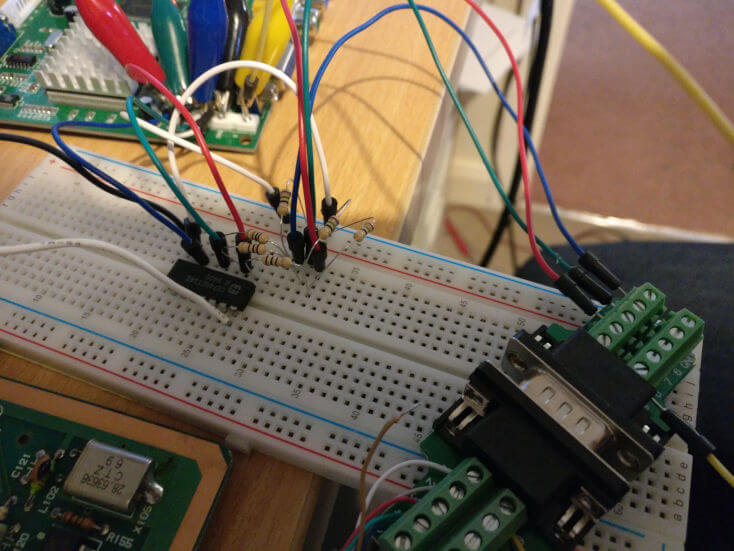
Here’s the circuit on solderless breadboard. I had some weird interference with this setup but once I confirmed that the basics were working I actually soldered it up on some protoboard and the interference went away. I picked up the +5V and GND from the pin header next to the ISA slots.
It seems the red channel is having some problems on my protoboard version (an oscilloscope confirms that the Amstrad is generating the signal OK, it’s just the converter output that’s dead). I’m going to put it down to either my dodgy soldering or a faulty component somewhere.
Also of note is the sync signal - Amstrad actually invert it along with everything else in their monitors, but my GBS-8200 didn’t like the inverted signal, so I just hooked it up as-is.
Here’s an example of the output from this setup, a photo of the monitor displaying a sample image from Amstrad’s bundled GEMPaint app - all of my original 30 year old 5.25” system disks work fine!
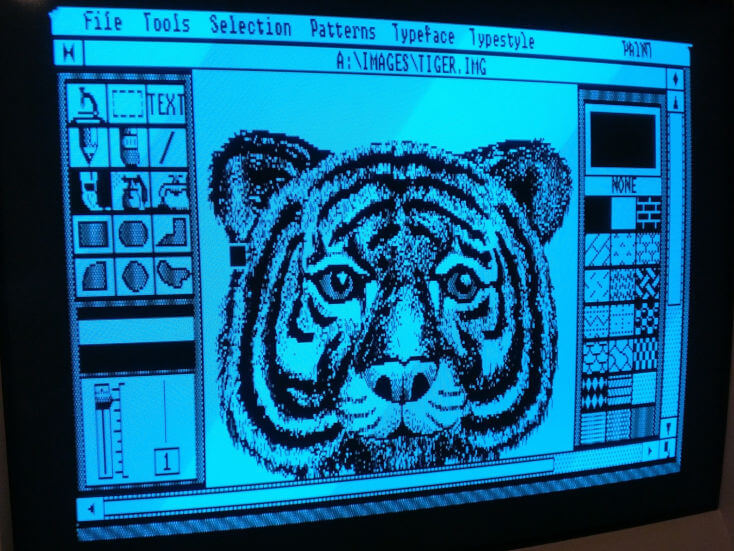
It’s very blue due to the red channel not working but the image quality is excellent for a first attempt (it’s very sharp IRL but taking photos of CRT monitors is never easy). There’s a small amount of distortion on the first couple of rows of pixels which I’m hoping is something to do with the speed of the Schmitt trigger, so it’s not a huge concern for now.
TODO: Many Improvements Needed!
I’m not done yet, and I’ll be writing up the next steps in another post. But here is the plan for the immediate future:
- Obtain TC74HC04 hex inverter chips and their cheaper brethren the 74LS04 to experiment with.
- Build a “pull both” circuit similar to this one for the Commodore 128. Without this I’m losing the Intensity signal and only have 8 out of the possible 16 CGA colours. I’m intrigued about the effect of including the mysterious “black” signal as well now, knowing that this is what Amstrad do in their monitors. Thankfully the hex inverter IC provides enough inverters to experiment with this.
- Investigate the situation with IBM brown. Without further processing, the CGA brown colour actually displays as dark yellow when converted. The IBM 5153 monitor has some circuitry built in to correct this. It may be that I’ll need to include this too, although looking at Amstrad’s schematics it doesn’t seem they made a similar effort. I’m probably going to have to obtain an Amstrad PC-CM monitor and some kind of palette generator software to see what it looks like.
- Get some PCBs etched
- Bundle everything up nicely and release as open source hardware, perhaps even as a Hacktoberfest project.
Update! I’ve now implemented most of the above and built a prototype. Check out my Amstrad PC1512 to RGB adapter prototype here!.
If you liked this post please consider following me on Instagram or BlueSky!