

The Amstrad PC1512 Video Liberator - Prototype
In my last post I explored the possibility of converting the Amstrad PC1512 video output into something useful, but came up against some problems. It’s been nearly a month since that post, so here’s an explanation of what I’ve been up to.
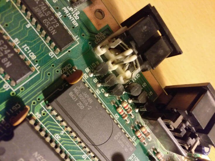
The main problem I had with my inverter was the blue hue to everything - it turns out that this was actually caused by a faulty transistor on the Amstrad motherboard. The 6 video channels (red, green, blue, intensity, black, and sync) are all configured as open collectors with 2SC2120-Y NPN transistors (pictured below). These transistors are pretty hard to track down - they were used in 80s hi-fi equipment, so no big surprise that they’d show up in an Amstrad I guess. Once I found a source it took a few weeks for them to arrive from China. Although the red channel was problematic, once I removed all 6 another one also tested as faulty, so I’m glad I replaced the lot. Then my colours were back to normal!
You may also recall that I’ve been testing with a Gonbes GBS-8200 video upscaler and a VGA monitor. I’ve now decided that a period correct 15kHz RGB monitor will be more useful as a test device, so I’m using an Atari SC1425 connected via RGB SCART. This also means that we could use a TV or even a PVM-type monitor. More importantly, it’s wired in such a way that I can plug straight into the Gonbes VGA input if I choose to. This gives us lots of options!
Progress
So without further ado, lets have a look at everything I’ve achieved since that previous post. Lets refer back to our list:
- Obtain TC74HC04 hex inverter chips and their cheaper brethren the 74LS04 to experiment with.
- Build a “pull both” circuit similar to this one for the Commodore 128. Without this I’m losing the Intensity signal and only have 8 out of the possible 16 CGA colours. I’m intrigued about the effect of including the mysterious “black” signal as well now, knowing that this is what Amstrad do in their monitors. Thankfully the hex inverter IC provides enough inverters to experiment with this.
Investigate the situation with IBM brown. Without further processing, the CGA brown colour actually displays as dark yellow when converted. The IBM 5153 monitor has some circuitry built in to correct this. It may be that I’ll need to include this too, although looking at Amstrad’s schematics it doesn’t seem they made a similar effort. I’m probably going to have to obtain an Amstrad PC-CM monitor and some kind of palette generator software to see what it looks like.Get some PCBs etched- Bundle everything up nicely and release as open source hardware, perhaps even as a Hacktoberfest project.
I got a few different inverter chips, but I’m pleased to report that after testing the cheapest option - the 74LS04 - works just as well as the others. So that’s the one I’ll be sticking with.
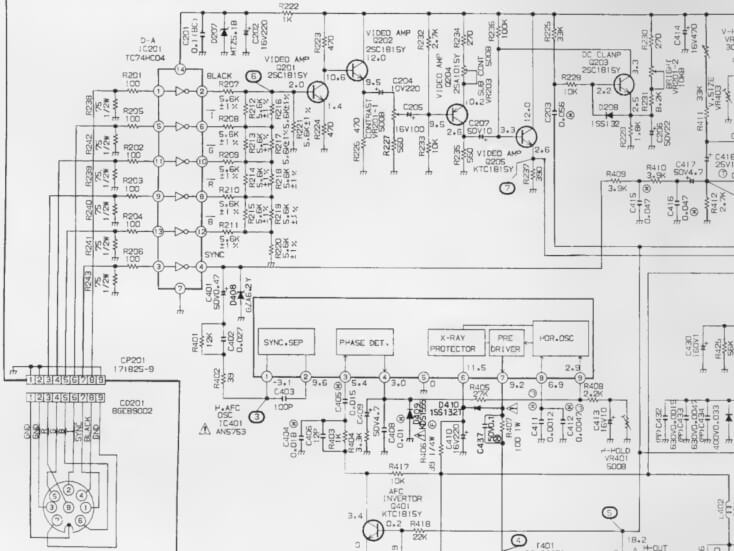
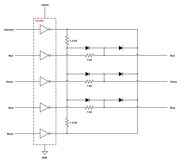
I also incorporated the “pull both” functionality - except in my case I pulled in the “black” output as well as the intensity. I’m still not 100% sure on what this does, but my testing shows that the output is a little bit brighter (and maybe even a bit sharper) with this connected, so it made sense to include it. Amstrad did on their original schematic (below) so why not.
Finally, I set up a repo to start documenting this all as an open hardware project, which I’m using for Hacktoberfest. Releasing something useful to the community! Essentially it will be a condensed version of these blog posts.
The Perfboard Prototype
Anyway, by this point I’m sure you’re itching to see the prototype, so here it is, as implemented on perfboard:
Front:
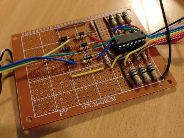
The yellow wires at the bottom show the path of the intensity signal (ignore the yellow-green-blue wires that go off to the left - they’re actually the RGB output). The grey wires at the top of the picture are the black signal. I wired up all 6 inverters on the 74LS04 just in case I needed to invert the sync signal as well, but this turned out to be unnecessary so I’m actually only using 5.
Back:
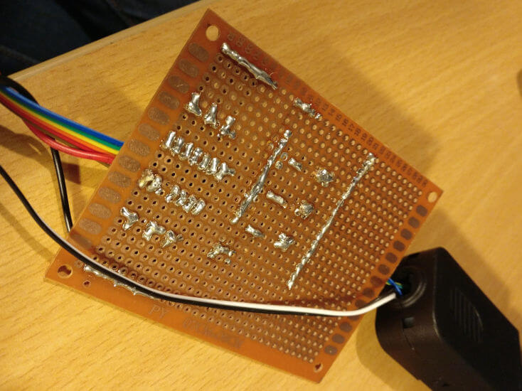
The black and white wires running under the board are the ground and sync, which I’ve just wired directly to the output socket (the sync goes to pin 13 of the VGA connector, and then on to pin 20 of the SCART plug). I actually improved this after the photo was taken and integrated it all onto the one board, eliminating the dangling wires.
The traces either side of the board (top and bottom left of photo) are grounds for the pulldown resistors, while the other two longer traces tie everything together for high and low sides of the “pull both” circuit.
Test Output:
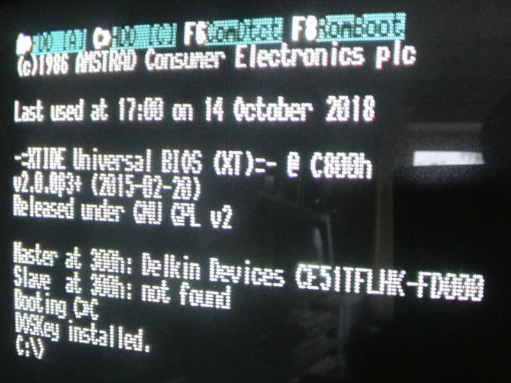
This photo actually lets on a little bit more than meets the eye - the F keys listed at the top of the screen (by the XT-IDE) are brighter than the rest of the text. This is because they’re using the “white” CGA colour rather than the “light gray” that the rest of the text uses, and proves that the intensity is doing its job. This can be confirmed very easily by disconnecting the intensity, which makes this brighter text the same colour as the rest.
The picture may seem a little blurry but that’s just my phone struggling to focus - it’s really sharp IRL - not to mention those beautiful scanlines!
Schematic
Finally, here’s the schematic of what I have so far:
TODO
I still haven’t fully tested this as I’m having some problems on the software side of things. I’m struggling to run the included GEM in colour mode as I don’t have a manual, but that will allow me to test further. Also I can’t get any games to run. I think this is probably a result of my ill-advised decision to run MS-DOS 5 on this thing, which is leaving very little free RAM for anything else. I found a copy of MS-DOS 3.31 which should allow me to keep my 512MB CompactFlash card while reducing my memory overhead by a fair bit. Then I can further test and refine the circuit!
I have spotted a couple of minor issues that I want to address soon:
- I’m not sure whether to have diodes on the intensity and black signals. I think the transistors on the motherboard should be serving this purpose, but it still seems odd to just connect them together. I think I’ll include some in the final design.
- There’s an ever so slight “ghosting” on the monitor on full screen, full colour images. It’s still pretty sharp but it’s not perfect. I’ve read that including decoupling capacitors in various places can reduce this, so I’m going to try incorporating some into the design.
- Investigate the situation with IBM brown. Without further processing, the CGA brown colour actually displays as dark yellow when converted. The IBM 5153 monitor has some circuitry built in to correct this. It may be that I’ll need to include this too, although looking at Amstrad’s schematics it doesn’t seem they made a similar effort. I’m probably going to have to obtain an Amstrad PC-CM monitor and some kind of palette generator software to see what it looks like.
- Get some PCBs etched
Until next time!
If you liked this post please consider following me on Instagram or BlueSky!